I just purchased a Bachmann Dynamis (US version), ProBox, and Bachmann 5A power booster. However, nowhere in the Bachmann documentation does it explicitly tell you how to connect the power booster if you have a Dynamis mounted on a ProBox (the Bachmann power booster user manual never even mentions the ProBox). Here's how I believe you're supposed to connect the Dynamis command station, ProBox, and 5A power booster:
[NOTE: BACHMANN HAS CONFIRMED THAT THE DRAWING IS CORRECT.]
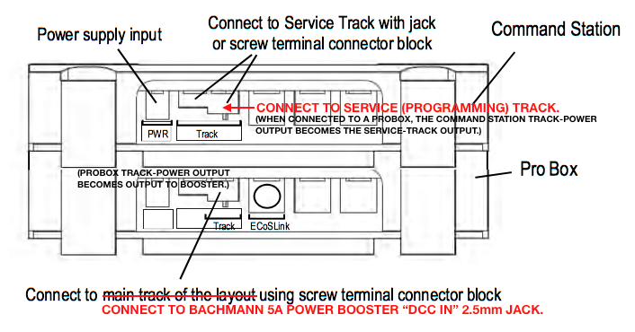
Main-track 5A power booster hook-up:
ProBox TRACK POWER --> power booster DCC IN --> power booster POWER OUT --> MAIN TRACK
Cable required: 2.5mm sub-mini plug-to-bare wire: [this cable is now provided.]
tip: unused
ring = positive (red)
sleeve = negative (black)
1. Attach the two bare wires to the green screw-terminal connector block on the ProBox --> TRACK POWER output.
2. Connect positive (red) wire to left terminal-screw. Connect negative (black) wire to right terminal-screw.
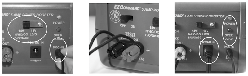
3. Insert the other end of the cable, the 2.5mm sub-mini plug, into the power booster --> DCC IN jack.
4. Connect bus wire to large POWER OUT screw-terminals on the power booster and connect to the MAIN TRACK.
Service-track (low-voltage) power hook-up:
Dynamis command station TRACK POWER --> SERVICE TRACK
Cable required: 3.5mm (1/8") mini plug-to-bare wire: [this cable is now provided.]
A. Create an electrically isolated track section using insulated joiners on both rails to use as a short service track (programming track).
B. Insert the 3.5mm mini-plug (1/8") into the Dynamis command station --> TRACK POWER output jack (which, when attached to a ProBox, is actually now the service-track output). [Alternatively, you can also just connect bare wires to the Dynamis command station --> TRACK POWER screw-terminal connector block.]
C. Attach the two bare wires on the other end of the cable to the SERVICE TRACK, observing correct polarity (e.g., RED = right rail; BLACK = left rail).
Questions:
• Are the procedures as described above all correct?
• At what amperage (i.e, when a short occurs) does the power booster trigger a power-off system shut-down?
[NOTE: BACHMANN HAS CONFIRMED THAT THE DRAWING IS CORRECT.]
Main-track 5A power booster hook-up:
ProBox TRACK POWER --> power booster DCC IN --> power booster POWER OUT --> MAIN TRACK
Cable required: 2.5mm sub-mini plug-to-bare wire: [this cable is now provided.]
tip: unused
ring = positive (red)
sleeve = negative (black)
1. Attach the two bare wires to the green screw-terminal connector block on the ProBox --> TRACK POWER output.
2. Connect positive (red) wire to left terminal-screw. Connect negative (black) wire to right terminal-screw.
3. Insert the other end of the cable, the 2.5mm sub-mini plug, into the power booster --> DCC IN jack.
4. Connect bus wire to large POWER OUT screw-terminals on the power booster and connect to the MAIN TRACK.
Service-track (low-voltage) power hook-up:
Dynamis command station TRACK POWER --> SERVICE TRACK
Cable required: 3.5mm (1/8") mini plug-to-bare wire: [this cable is now provided.]
A. Create an electrically isolated track section using insulated joiners on both rails to use as a short service track (programming track).
B. Insert the 3.5mm mini-plug (1/8") into the Dynamis command station --> TRACK POWER output jack (which, when attached to a ProBox, is actually now the service-track output). [Alternatively, you can also just connect bare wires to the Dynamis command station --> TRACK POWER screw-terminal connector block.]
C. Attach the two bare wires on the other end of the cable to the SERVICE TRACK, observing correct polarity (e.g., RED = right rail; BLACK = left rail).
Questions:
• Are the procedures as described above all correct?
• At what amperage (i.e, when a short occurs) does the power booster trigger a power-off system shut-down?