News:

Please read the Forum Code of Conduct   >>Click Here <<

Main Menu
Menu

Show posts

This section allows you to view all posts made by this member. Note that you can only see posts made in areas you currently have access to.

Show posts Menu

Messages - Joe Satnik

#211
Large / Re: 3-truck Shay drivetrain and lubrication
October 04, 2014, 06:22:50 PM
Dear George,

I commend you for volunteering to help, and congratulate you on your success. 


Sincerely,

Joe Satnik

Perhaps someone handy could create a virtual medal with Bach-Man's image on it. 

He is, of course, the original model train trouble-shooting super-hero...
#212
Large / Re: Stalling
October 04, 2014, 05:56:23 PM
Dear fhenn,

Check to see if your front 4 wheel pony truck is not turned in the wrong direction.   

This would cause a short on your track, stopping the loco and tripping the circuit breaker in the power pack. 

The arrow underneath the truck should be pointed forward.

An Ohm-meter should show near-zero Ohm connections between all electrical pickup wheels on the same side of the loco,

and the resistance of the motor (10 Ohms or so?) between any right pickup wheel and left pickup wheel.

Hope this helps. 

Sincerely,

Joe Satnik
#213
Hey, Bob. 

Whooo-Eeeee!

Yeee-Ha !

Congrats on your find. 

Careful not to add too many B units to the middle, as you'll have no room at the end of your train for passenger or freight cars.

Joe

#214
HO / Re: HO crossover track
October 01, 2014, 02:39:49 PM
Dear All,

The analog DC controller does not power the DC locomotive on the DCC track.  

It only provides an analog reference voltage (proportional to your desired speed and direction) to the EZ-Command DCC controller,

which interprets it and "stretches the zeros" of the DCC signal to the track, which fools the DC locomotive into running.  

Problem is, though, that when the DC loco is stopped and still resting on the DCC tracks, the full power DCC signal will "cook" the poor DC loco's motor.

Get your DC loco off the tracks as soon as possible after stopping,

or park it on a siding with one isolated rail that can be shut off (from the track DCC signal) with an electrical switch.  

Hope this helps.

Sincerely,

Joe Satnik

Edit: Spelling      
#215
Large / Re: new scratch building project
September 29, 2014, 12:25:54 PM
Dear Tanker,

If you only need to drop a few volts, the Dallee Diode bridge circuit with extra diodes works well:

http://www.dallee.com/PDFs/MotorDiodeDrop.pdf

It wouldn't be as efficient as a chopped output voltage reducer, but those are electrically pretty noisy.

About your small voltage motor:

Power = Volts x Amps.

If you have a smaller voltage motor, it will have to draw larger amps to do the same work, thus overloading the RX board. 

Adding weight will draw more amps, making the overload problem worse.

Hope this helps. 

Sincerely,

Joe Satnik
#216
HO / Re: HO crossover track
September 21, 2014, 04:55:59 PM
Dear Rook,

Please consider eliminating the DC power pack's speed/direction output from the rails of your layout.

(The DC power pack's Accessory Output terminals can/should remain to power the dual-coil solenoids that move the points of your turnouts and crossovers.) 

The remote crossover tracks (44575 Left and 44576 right) need extensive modifications

(cuts to rails and foils) to separate the 2 main lines from each other for DC block operation.

One DCC source sent everywhere works best for layouts using these crossovers. 

Hope this helps.

Sincerely,

Joe Satnik
#217
Dear B,

Your picture is worth a thousand words. 

It's a good idea to have the track power fed on the points side of the turnouts.

Move your curved terminal-rerailer to the left most semi-circle in your picture.   

This may not solve all the problems, but it is a "start" to get back to a known configuration.

Bachmann's N E-Z Track turnouts are power routing.  I suspect that an internal rack-and-pinion driven electrical switch has jumped a tooth.

I suggest you buy a Volt-Ohm (multi-) meter to be able to measure voltages and resistances. 

Every hobbiest should have one.

If you have a Harbor Freight close by, you may find a multi-meter on sale for much less than 10 bucks.

Sometimes they have a coupon deal for free or nearly free. 

Hope this helps.

Sincerely,

Joe Satnik
#218
HO / Re: LED turnout indicators
September 18, 2014, 11:55:21 PM
Hi, Elnovato,

You could use a 3-pole-double-throw (3PDT On-On) switch.

Two poles would charge and discharge capacitors to drive the twin coils, the 3rd pole would light either the

green or red LED.

             / ------------------------------reverse coil
Cap1+--/     Pole A

                --------------WWW--------P.S.+
                           l     Charge
                           l     Limiting
             / --------l     Resistor
Cap2+--/    Pole B

                -------------------------------normal coil

                    /-----WWW---->l------------P.S.(-)
P.S.+--------/         Res.   Rev. LED
                      Pole C
                     ------WWW---->l-----------P.S.(-)
                              Res.  Norm. LED

P.S.(-)---------Cap1(-), Cap2(-), twin coil common

P.S. = DC power supply

Haven't figured component values out yet. 

Hope this helps.

Sincerely,

Joe Satnik
#219
HO / Re: #6 Left and Right crossovers
September 17, 2014, 11:45:51 PM
Hi, Gary. 

Are you running a newer DCC control system or an old analog DC control ?

Thanks.

Joe Satnik
#220
HO / Re: LED turnout indicators
September 17, 2014, 10:55:32 PM
Dear Elnovato,

Please let us know what brand and part number turnout you have.  

If it is Bachmann's and has a metal frog, I have a relatively simple circuit for your lights.

Thanks.

Sincerely,

Joe Satnik

Edit: Back to the drawing board.  Simple circuit I thought of doesn't work properly.   
#221
HO / Re: Turn table problem
September 14, 2014, 04:32:42 PM
Try cleaning and lubing the bridge to siding electrical contacts.
#222
On30 / Re: Problems with an insulated reversing loop
September 14, 2014, 10:56:45 AM
Hi, Bill.

Are there any frog powering wires under your turnouts?  Are they hooked up to anything?

What method are you using to reverse the polarity?

Can you somehow post a diagram or picture of your layout, or at least the shorting location and the turnouts around it?

AnyRail.com layout CAD program would be an excellent way to do this.  (Download is free for first 50 track pieces.)

Otherwise, you could code your layout to describe it better.  

Descriptions should begin and end at a turnout end:

For example, Turnout 1 is a left.  It has a points end, divergent end and mainline end. Its points end is facing west.

Its divergent end is connected to a double insulated joint, curves right, is conected to the output of the reverser, through a double insulator and connects back up to the main end of turnout 1:

T1LWD - DI- CR - RO - DI - T1LWM

A wye turnout could be coded as Y  with a Left, Right and Points end.

Any track section hooked up to the 2 output terminals of the DCC controller would have to be polarity (or "phase") designated.

Reverser output terminals  do not need to be designated.

Use compass designation for the rail, such as N, SE, etc.

DCC output terminal 2 connected to the South West rail would be DCC2SW

Write as many lines of code as needed until all turnout ends and power connections to the rails on your layout are mentioned.  

Thanks.

Sincerely,

Joe Satnik

Edit: Grammar, added "or phase", added "and power connections to the rails".
#223
General Discussion / Re: Code 100 N/S Rail
September 12, 2014, 05:37:09 PM
Dear Zug,

http://www.handlaidtrack.com/18in-Micro-Engineering-Code-100-Non-Weathered-Rail-p/17-100-c.htm

Another possibility, strip rails out of Flex or Semi-Flex track. 

My LHS just quoted me $3.33 for one piece of 38" Semi-Flex, two pieces would give 12' - 8" of rail.

Hope this helps. 

Sincerely,

Joe Satnik
#224
HO / Re: Yet another Locomotive Project
September 11, 2014, 10:02:17 AM
Dear All,

Had your coffee yet?  Good.

Welcome to (old school) Electrical Engineering.

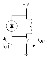
The reverse diode flash is caused by inductive kickback from the motor.

Any inductor, which includes a motor winding, is an energy storing device. 

It stores its energy in "current" (I), which is measured in Amps.   

Just the opposite is a capacitor, which stores its energy in "voltage" (V), which is measured in Volts. 

It is hard to get current going in an inductor. 

Once you get it (I) going, it wants to keep going. 

If you abruptly turn off the power to the inductor, it will try to keep the current going. 

https://www.youtube.com/watch?v=auvh0H4QvbY

That current has to go somewhere. 

In this case the reverse LED happens to be (conveniently) available to absorb (provide a non-destructive path for) that current, thus the flash. 

If your front LED is wired to run only in the forward direction, you will see it flash after you are running in reverse and abruptly turn off the power.

Inductive kickback can destroy sensitive electronics,

so in many cases reverse diodes are wired across inductive loads to absorb it. 


You may wake up now. 

Hope this helps.

Sincerely,

Joe Satnik
#225
N / Re: Figure 8 using E-Z track
August 31, 2014, 06:10:21 PM
Isn't trig fun?

What I came up with:

Given

crossing degrees "CRDG",

crossing length "CRL"

curve radius "R",

and track bed width "TBW",

a mathematically perfect Figure-8 has the following formulas:

Overall Width = 2R + TBW

Straight length between opposing curves = 2R x Tangent(CRDG/2)  (Good for an up-and-over Figure-8.)

Straight length between crossing and curve = R x Tangent(CRDG/2) - CRL/2     (There are 4 of these straights per Figure-8.)

Overall Length = 2R x [1+Secant(CRDG/2)] + TBW, where Secant is the same as 1/Cosine

If you are running fence-to-fence on your table top, add another TBW to both Overall Length and Overall Width for loco and rolling stock overhang.

It is possible to create an HO 18"R and 22"R "Double-Cross-Demolition-Derby" Figure-8 using  four 90 degree crossings (and their included 2" pieces).

Try it out on Anyrail.

22"R and 26"R (actually, any 4" difference in radius) would work in HO too, but would be incredibly long and wide.  

If anyone claims I did, I will categorically deny that I have ever walked around wearing a hat in the shape of a Figure-8.

Hope this helps.  

Sincerely,

Joe Satnik

Edit: Added HO references.